Pittler T&S GmbH - already a force to be reckoned with in the field of skiving for many years - can rely on the enormous wealth of experience of its setters. Nevertheless, this still young manufacturing process always holds new challenges. It is difficult to imagine what happens in detail in the machine. For this reason, Pittler began developing its own software for simulating the skiving process about two years ago: SkivePit.
SkivePit provides technologists and setters at Pittler T&S GmbH with a better understanding of what happens inside a Pittler SkiveLine machine through comprehensive functions such as calculating gear and tool data, as well as when virtually mapping the manufacturing process. For this purpose, gear data of the component to be peeled as well as the data of the tool (Figures 1 and 2) are stored in the software. The data usually comes from the production drawings. However, new peeling tools can also be created from the preliminary design to the finished tool contour and the contours exported to a CAD system for further tool design.
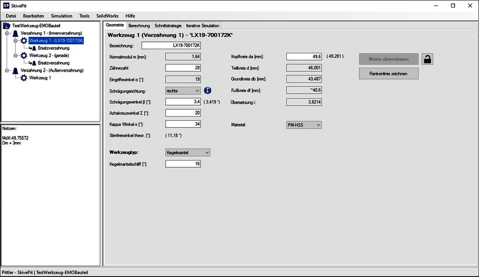
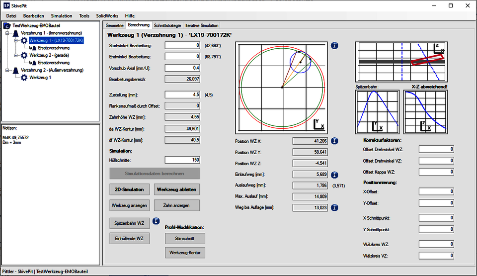 Figure 2 Input, calculation and visualization of the mold process parameters as in a Pittler SkiveLine machine
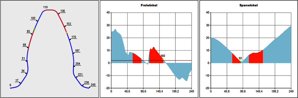
By simulating the cutting motion of the tool, the resulting tooth space can be displayed not only in the classic face section, i.e. in a horizontal section through the component. It is also calculated which areas of the tool cutting edge are actually engaged at which point in the cutting movement (Figure 3, left). This results in the contour of the generated chip (Figure 3, right).
 Figure 3 left: Face section of the tooth space of an internal gear (blue) and representation of the tool (gray). The red dots intersect the component at the time under consideration. right: Representation of the tooth space in blue, representation of the generated chip shape in orange.
The system calculates the effective rake and clearance angles of the cutting edge based on a rolling simulation (Figure 4). Based on the cutting wedge, which is shown two-dimensionally in many reference books for turning or milling, it is possible to calculate by hand with simple kinematics how the mentioned angles change during the cut and which forces act. In skiving, this is difficult to do without computer support. However, clearance and rake angles have a major influence on the tool life of a tool. In skiving, they can be changed by design modifications to the tool, but also by a different positioning in the working area. The possibility of calculating the cutting edge angles is used to gain a much better understanding of the process and the tool design.
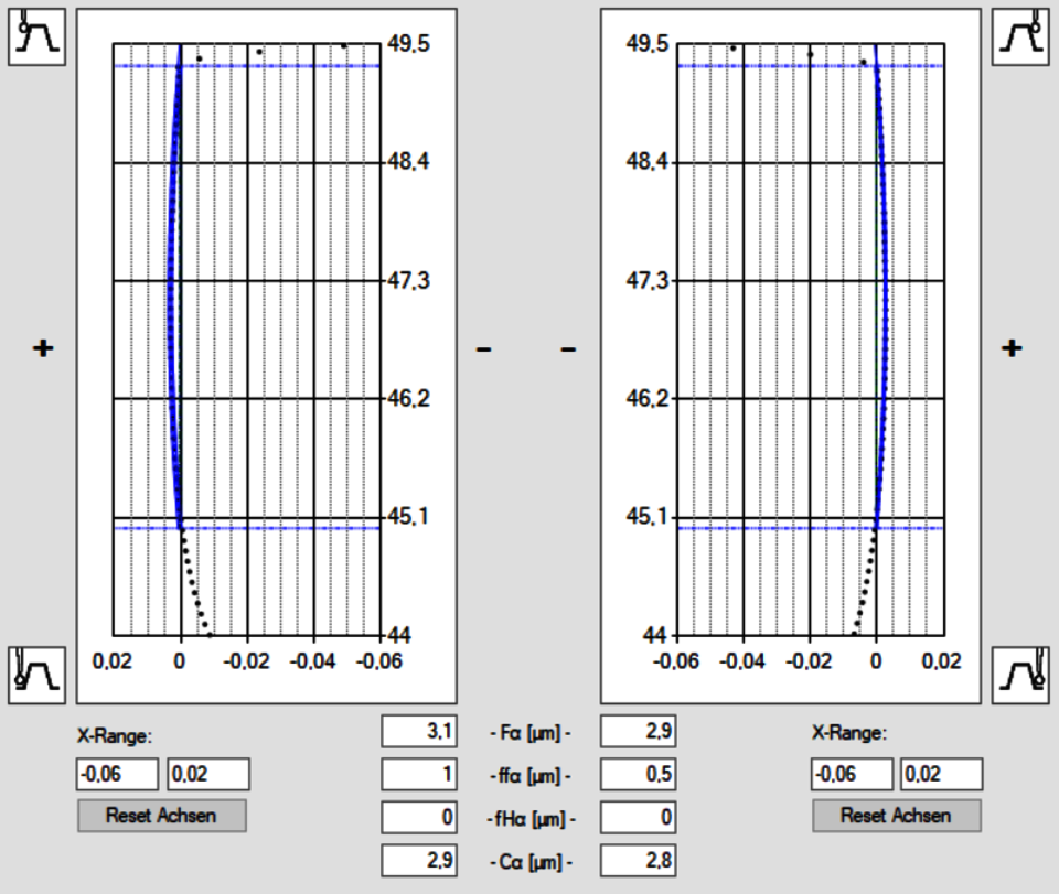
As with the real design, the simulated tooth space can be measured after the cut. For this purpose, SkivePit offers a virtual gear measurement to be able to evaluate the result.
With the help of the presented and many more functions SkivePit enables to make the process in the machine tool visible and understandable. Difficulties during setup can be localized and eliminated. But also the tool design according to own requirements gets more and more importance at Pittler.
In the future, the bridge will be built to a real digital twin and data will be exchanged directly with the machine tool. In this way, the setter will be able to virtually test the process in advance, identify problems and adjust them even before a chip has fallen on the machine.

Leitung Vertrieb | Sales Manager
Christian Ballweg
T.: +49 6074 4873 256
christian.ballweg@pittler.de
PITTLER T&S GMBH
Johannes-Gutenberg-Str. 1
63128 Dietzenbach


